
Variability models, feature diagrams (FDs) ahead, are commonly used to document product line (PL) requirements. They are also often used during product derivation where they are fed to configuration tools which support semi-automated feature selection. Configuration tools facilitate this task by automatically propagating the decisions made and by ensuring their overall consistency. However, most feature-based configuration (FBC) tools assume that there exists a single monolithic FD and do not account for configuration processes that are distributed among various stakeholders who have specific concerns and who intervene at different moments. Our collaborations with industry have confirmed the need for techniques and tools that support such complex configuration processes and better chunking of the FD into coherent views. We recall the basics of multi-view FDs and feature configuration workflows before delving into the details of our extensions to SPLOT and YAWL.
Table of Contents
Multi-view Feature Model
Two challenges that FBC techniques fail to address in a satisfactory way are (1) tailoring the configuration environment according to the stakeholder's profile (knowledge, role, preferences...) and (2) managing the complexity resulting from the size of the FD. We address these challenges by extending FDs with multiple views that can be used to automatically build FD visualisations. A view is a streamlined representation of an FD that has been tailored for a specific stakeholder, task, or, to generalize, a combination of such elements--which we call a concern. Views facilitate configuration in that they only focus on those parts of the FD that are relevant for a given concern. Using multiple views is thus a way to achieve separation of concerns (SoC) in FDs. SoC helps making FD-related tasks less complex by letting stakeholders concentrate on the parts that are relevant to them while hiding the others. Further tailoring of the visualisations can be achieved through the selection of three alternative visualisations: (1) "greyed out", (2) "pruned" and (3) "collapsed".
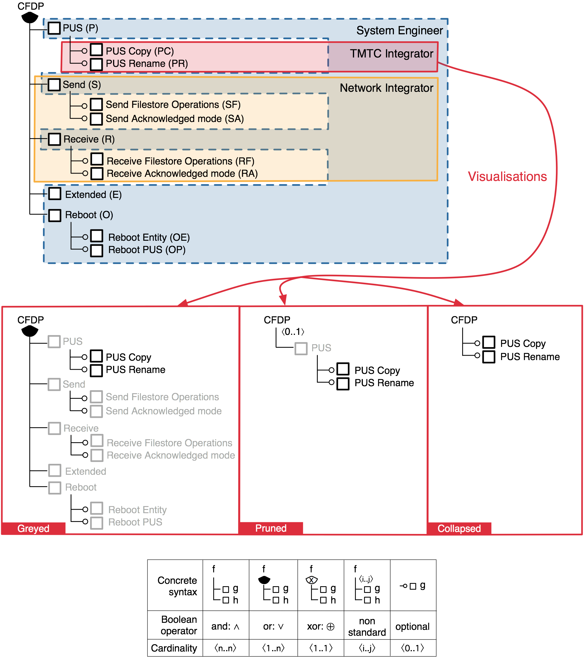
Let us illustrate the concept of multi-view FD on the Spacebel case. Spacebel is a Belgian software company developing software for the aerospace industry. We collaborate with Spacebel on the development of a SPL for flight-grade libraries implementing the CSSDS File Delivery Protocol (CFDP) [Hubaux2009]. CFDP is a file transfer protocol designed for space requirements, such as long transmission delays and specific hardware characterised by stringent resource limitations. Spacebel built a SPL of CFDP libraries, where each library can be tailored to the needs of a specific space mission. A simplified excerpt of this FD appears in the upper part of Figure 1. The principal features provide the capability to send (Send) and receive (Receive) files. The Extended feature allows a device to send and receive packets via other devices. The Reboot feature allows the protocol to resume transfers safely after a sudden system reboot. PUS stands for Packet Utilisation Standard, part of the ESA standard for transport of telemetry and telecommand data (TMTC). The PUS feature implements the CFDP related services of this standard.
CFDP typically handles five different stakeholder profiles. Spacebel decides which features are mature enough for the mission, while leaving as much variability as possible. The Reseller can, depending on the contract, or for other commercial reasons, further configure the product. The system engineer makes initial high-level choices and passes the task of refining these choices on to the network integrator and the TMTC integrator who handle the technical aspects of the CFDP. The configuration options of interest for each of these profiles are thus different and limited in scope.
A major problem is that access rights to these configuration options are currently informally defined and FDs offer no way to do so. In the absence of clear access specifications, a simplistic policy has been implemented: all profiles have access to all configuration options. A reported consequence is that sometimes the system engineer does not have sufficient knowledge to fully understand low-level options and make decisions. The results were incorrect settings, e.g., inappropriate CPU consumption or excessive use of memory for a given hardware. Similarly, the integrators were not aware of general decisions and could make inconsistent choices wrt. the missions' goals. The changing context also demands flexible definitions of access policies. For in- stance, there can be variations in the access rights (e.g., the integrators are granted access to more features) or stakeholder profiles (e.g. a dedicated File System integrator might be needed in some projects).
Solving that problem requires being able to specify which parts of the FD are configurable by whom. This can be achieved easily by augmenting the FD with a set views, each of which consists of a set of features. But this makes views abstract entities. To be effectively used during FBC, they need to be made concrete, i.e. visual. We call a visual representation of a view a visualisation. The goal of a visualisation is to strike a balance between (1) showing only features that belong to a concern and (2) including features that are not in the the concern but that allow the user to make informed decisions. For instance, the PUS copy feature is in the view of the TMTC integrator, but its parent feature PUS is not: How will that influence the decision making process? To tackle this problem, we see three visualisation alternatives with different levels of details. Figure 1 shows the views of the System Engineer, TMTC Integrator and Network integrator. Let us zoom in on the three possible visualizations and illustrate that on the view of the TMTC Integrator.
The greyed visualisation is a mere copy of the original FD in which the features that do not belong to the view are greyed out (e.g. P, S, SF and SA). Greyed out features are only displayed but cannot be manually selected/deselected. In the pruned visualisation, features that are not in the view are pruned (e.g. S, SF and SA) unless they appear on a path between a feature in the view and the root, in which case they are greyed out (e.g. P ). Pruning can have an impact on cardinalities. As shown in Figure 1, the cardinality of CFDP is <0..1> whereas it is <1..5> (or-decomposition) in the FD. It has to be recomputed to ensure the consistency of the FD. In the collapsed visualisation, all the features that do not belong to the view are pruned. A feature in the view whose parent or ancestors are pruned is connected to the closest ancestor that is still in the view. If no ancestor is in the view, the feature is directly connected to the root (e.g. P C and P R). Similarly, cardinalities have to be recomputed for consistency reasons.
How to use views in SPLOT?
There are essentially two ways of specifying views. The most obvious is to enumerate, for each view, the features that appear in it, or equivalently, to tag each feature of the FD with the names of the views it belongs too. These are extensional definitions, which might be very time-consuming and error-prone if the FD is too big. A natural alternative is thus to provide a language for intensional definitions of views that takes advantage of the FD's tree structure to avoid lengthy enumerations. A simple query language like XPath is a good candidate to define views and retrieve the corresponding features. SPLOT supports that latter alternative, which is available in View Specification. Visualizations can be selected to configure views in the Interactive Configuration menu.
Feature Configuration Workflow
Views are only one side of a two-sided story. The second side addresses the scheduling of the configuration process. In essence, the idea is to specify the configuration process with a workflow, aka. business process. The combined formalism of the workflow with a set of views is called a feature configuration workflow (FCW). An FCW is thus composed of three basic elements: several views, a workflow and a mapping between them.
Among the variety of workflow languages, we picked YAWL as it is formal, has extensive tool support and is known to cover a large variety of real-world modelling patterns. YAWL is inspired by Petri nets. Its principal constructs are conditions and tasks, which roughly correspond to places and transitions in Petri nets. There are two special conditions, start and end. In Figure 2, each task, except for (loop) and Product release, denotes a configuration activity, and is annotated with the name of the stakeholder performing the configuration. Spacebel is split in two with a XOR split, meaning that only one of the outgoing transitions is executed, which captures well the optional nature of Reseller. System Engineer joins both paths and then splits again, but this time with an AND split, meaning that the TMTC and Network Integrator run in parallel. From there, the configuration process is either finished (Product release) or continues with System Engineer.
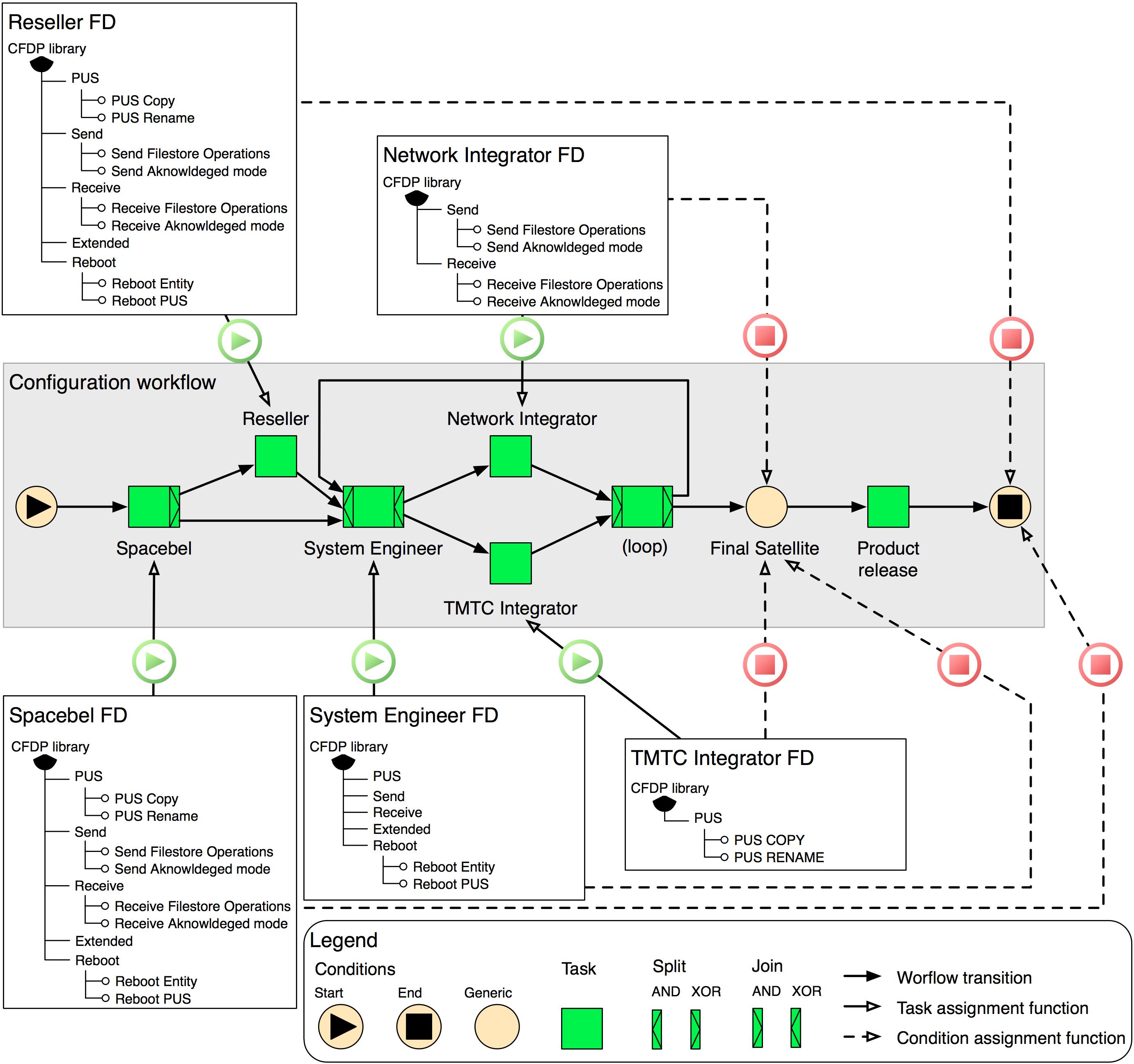
The views reported here are all derived from Figure 1 to which we added two actors, namely Spacebel and the Reseller. The mapping between the workflow and the views is defined separately for each view. The task denotes the starting point of the configuration whilst the condition represents the point at which configuration has to be finished. The task and condition are respectively called the start and stop of a view. In Figure 2, the Final Satellite stop, to which three views (System Engineer, Network Integrator and TMTC Integrator) point, indicates the group formed by these modules: as long as the stop is not satisfied, the loop has to continue. The two other views, including the optional Reseller view, map onto the output condition since their configuration time does not matter.
How to use FCWs in SPLOT?
SPLOT does not support workflow edition, analysis and execution. That part of the job is handed over to YAWL. The coming sections describe sections how it can be achieved in YAWL. Once a valid YAWL workflow is available, SPLOT can import it via the Workflow Management menu. Once imported, the workflow can be linked to the views of a given FD in the View Specification menu. The configuration can then be driven by YAWL.
FCW Toolset
The toolset we propose provides full-fledged support for workflow-driven FBC. Figure 3 captures the core components of the toolset. Before going through a typical use case scenario, let us first describe the role of the FCW Engine. The FCW Engine is a Java-based system that drives the configuration process. The duty of the engine is to manage the communication between YAWL and SPLOT. The FCW engine controls and records the progress of the FCW instances, the status of the tasks and conditions, the state of the configuration, and the log of the configuration activity. It also provides a control panel that allows to monitor all the FCW instances and to resume sessions that were closed.
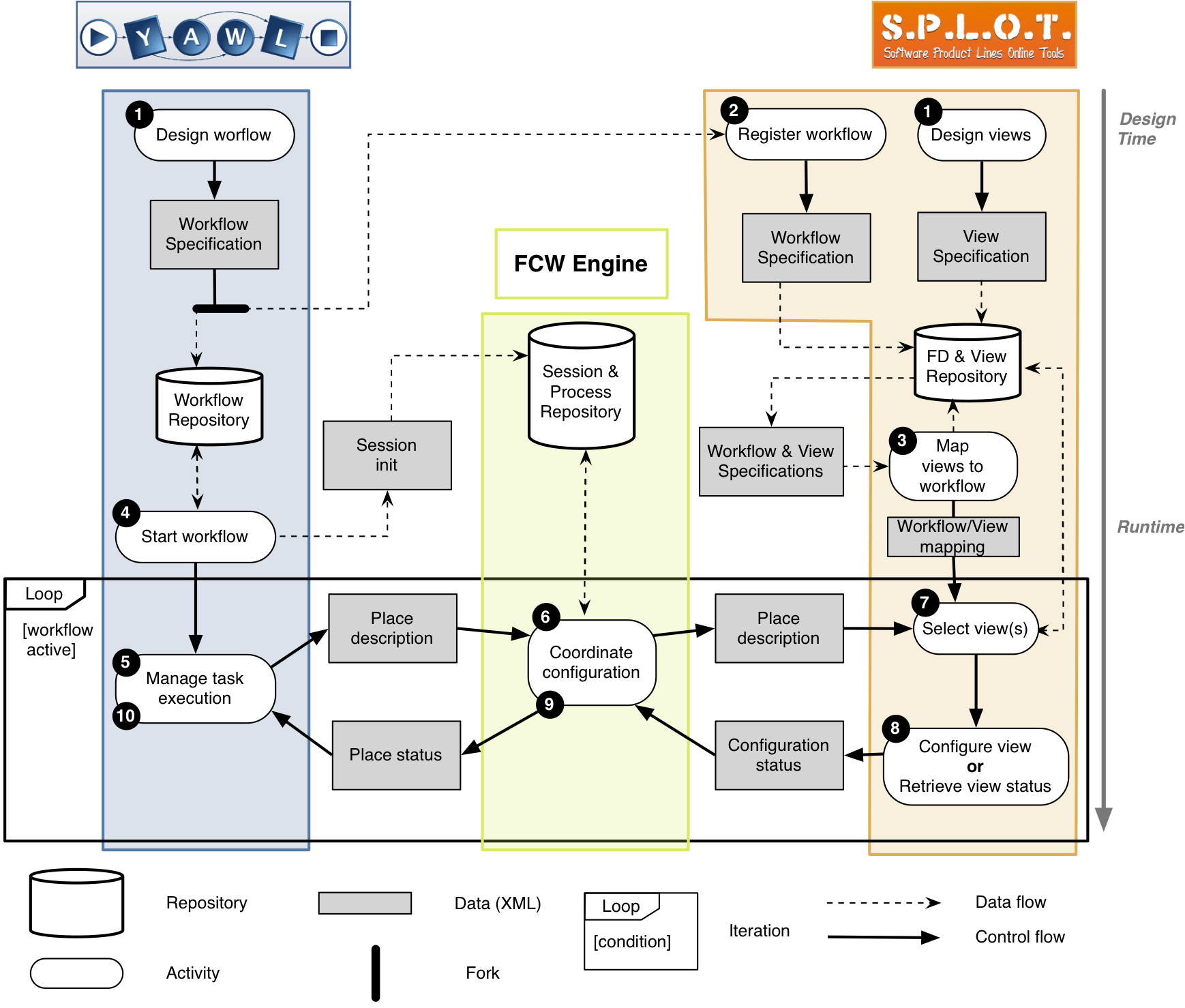
The scenario depicted in Figure 3 highlights the essential steps of the specification of a complete FCW (1-3), followed by the initialisation of the configuration session by an extension of YAWL (4) and the complete execution of the workflow resulting in the complete configuration of the product (5-10).
Installation Instructions
The installation of the toolset requires the installation of YAWL and the FCW Engine. The FCW Engine can either be connected to a local instance of SPLOT or an instance available online, like http://www.splot-research.org/.
Step 1 - Installing YAWL
- Download YAWL and follow the instructions for your operating system here. All the extensions have been tested with YAWL 2.1 with no guarantee of support for older versions.
- Go to ./YAWL4Study-2.1/bin, start the YAWL engine (StartEngine) and start the control centre (ControlCentre). This will start Tomcat and load all the necessary dependencies.
- Log in YAWL. By default, the login is admin and the password is YAWL.
Step 2 - Installing FeatureConfigurationWorkflowService
- Download the latest version of the Feature Configuration Workflow Service. The Feature Configuration Workflow Service is a service that maintains a communication bridge between YAWL and the FCW Engine.
- Move FeatureConfigurationWorkflowService.war into:
(I)./YAWL4Study-2.1/engine/apache-tomcat/webapps (the installation path may vary according to your version of YAWL) if you would like to run YAWL and Feature Configuration Workflow Service on the same instance of tomcat, or
(II)./apache-tomcat/webapps if you would like to run YAWL and Feature Configuration Workflow Service on different instances of tomcat.
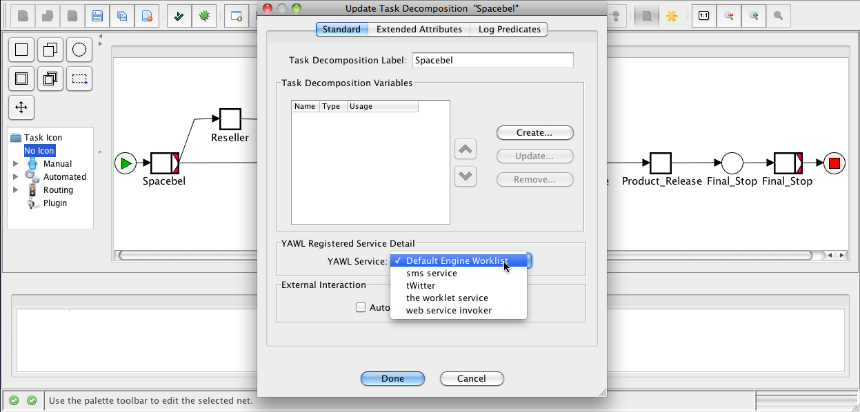
At design time, in the YAWL editor, every atomic task in a workflow specification has to be associated with a Default Engine Worklist service. Figure 4 shows how a Default Engine Worklist is assigned to a task of a workflow.
At design time, also, in the YAWL editor, for each task in a workflow, the URI of the Feature Configuration Workflow Service's responsible servlet to handle the communication, has to be assigned.
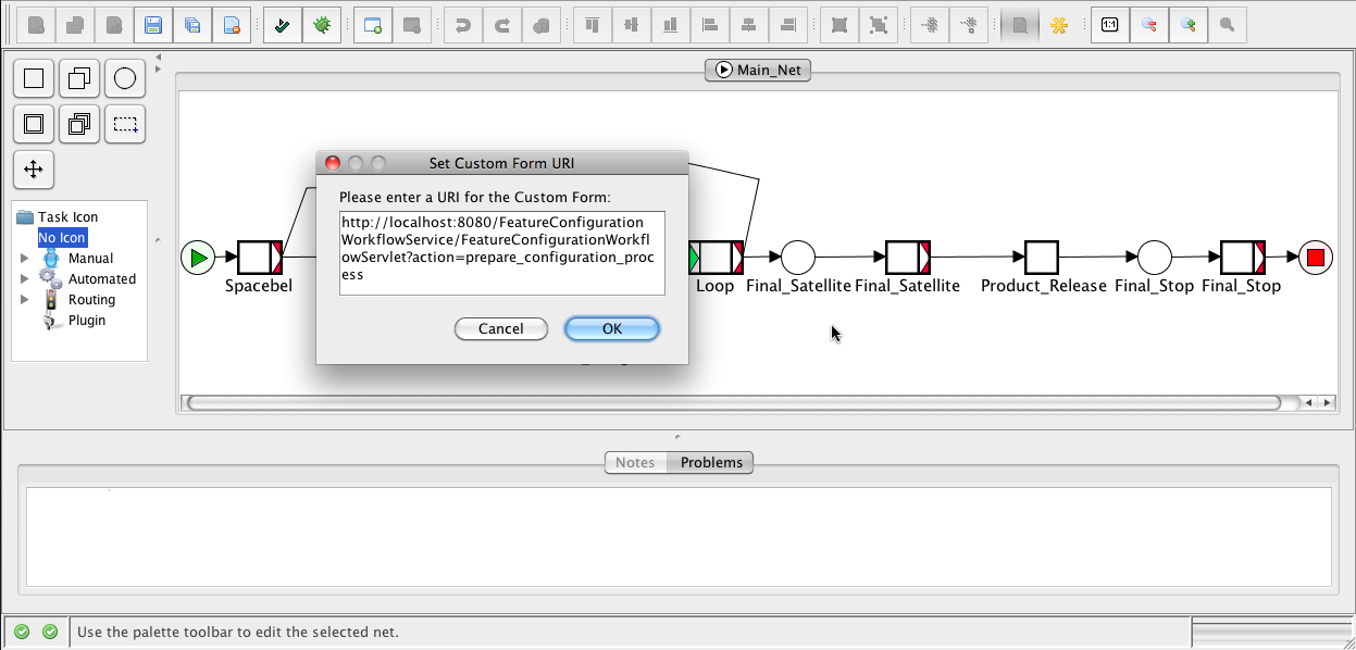
Figure 5 shows how FeatureConfigurationWorkflowServlet of Feature Configuration Workflow Service as a custom form, is assigned to a task of a workflow.
The URI must be:
http://localhost:pppp/FeatureConfigurationWorkflowService/FeatureConfigurationWorkflowServlet?action=prepare_configuration_process. pppp is to be replaced with the actual port number of the container which hosts the Feature Configuration Workflow Service.
Step 3 - Installing the FCW Engine
- Download the latest version of the FCW Engine.
- Move Coordinator.war into:
(I)./YAWL4Study-2.1/engine/apache-tomcat/webapps (the installation path may vary according to your version of YAWL) if you would like to run YAWL and the FCW Engine on the same instance of tomcat, or
(II)./apache-tomcat/webapps if you would like to run YAWL and the FCW Engine on different instances of tomcat.
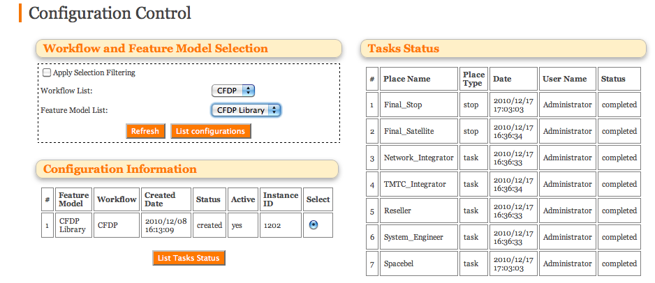
The Control Panel provided for the FCW Engine is illustrated in Figure 6 and can be accessed at http://localhost:pppp/Coordinator/index.html. pppp is to be replaced with the actual port number of the container which hosts the FCW Engine. It allows to monitor the configuration status of the different tasks and stops.
Step 4 - Connecting to running instances of the FCW Engine and YAWL
- Go to the Feature Configuration Workflow Service's registration page at
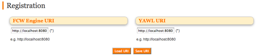
http://localhost:pppp/FeatureConfigurationWorkflowService/registartion.html. pppp is to be replaced with the actual port number of the container which hosts Feature Configuration Workflow Service. - Fill out the FCW Engine URI field as the URI of the FCW Engine instance. The value of this field should be in the form of http://localhost:pppp. pppp is to be replaced with the actual port number.
- Fill out the YAWL URI field as the URI of the YAWL instance. The value of this field should be in the form of http://localhost:pppp. pppp is to be replaced with the actual port number.
- Click on Save URI.
Figure 7 shows the registration page of Feature Configuration Workflow Service to fill out the YAWL and FCW Engine's URI.
Step 5.a - Installing SPLOT locally
- Download the latest version of SPLOT.
- Move SPLOT.war into./apache-tomcat/webapps. Note that SPLOT must run on a different instance of tomcat than the other components.
- Go to ./apache-tomcat/webapps/SPLOT/WEB-INF.
- Open web.xml.
- Change the paths to models and logs according to your environment.
Step 5.b - Connecting to a running instance of SPLOT
- Go to the FCW Engine's registration page at http://localhost:pppp/Coordinator/registartion.html. pppp is to be replaced with the actual port number of the container which hosts the FCW Engine.
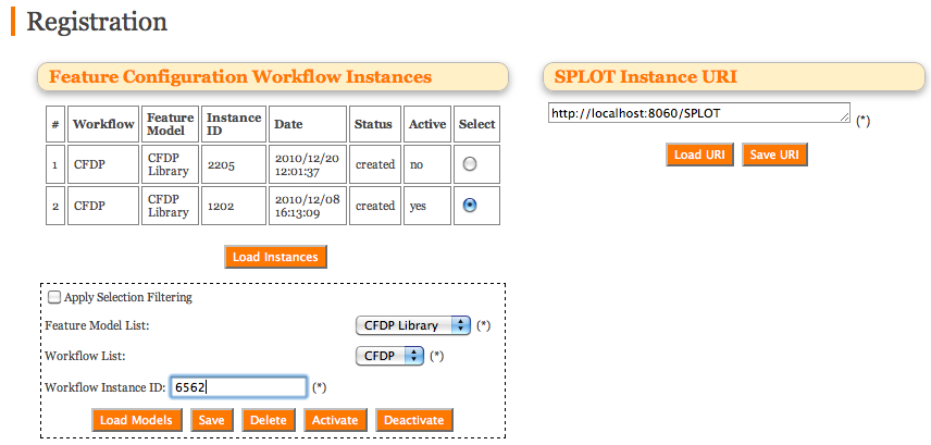
- Fill out the SPLOT Instance URI field. The value of this field should be http://localhost:pppp/SPLOT for local host and http://gsd.uwaterloo.ca:8088/SPLOT for the online SPLOT instance. pppp is to be replaced with the actual port number.
- Click on Save URI.
Active instances identify which FDs are involved in the configuration process. An example of SPLOT instance registered in the FCW Engine is shown in the upper right part of Figure 8. The figure also shows the current configuration sessions.
Getting Started
The video below showcases a typical use case of the toolset. It starts with the creation of a workflow in YAWL, it registration in SPLOT, the creation of the views and their mapping to the workflow. Then, the configuration process starts until the completion of the configuration of the final product. Finally, the monitoring controls provided by the Control Panel of the FCW Engine are quickly explored.

Related Publications
- An Interactive Multi-perspective Toolset for Non-linear Product Configuration Processes (tool demo), Ebrahim Khalil Abbasi, Arnaud Hubaux, Patrick Heymans, in Proceedings of the 15th International Software Product Lines Conference (SPLC'11), Munich, Germany.
- A Toolset for Feature-based Configuration Workflows, Ebrahim Khalil Abbasi, Arnaud Hubaux, Patrick Heymans, in Proceedings of the 15th International Software Product Lines Conference (SPLC'11), Munich, Germany.
- Towards Multi-View Feature-based Configuration, Arnaud Hubaux, Patrick Heymans, Pierre-Yves Schobbens, Dirk Deridder, in Proceedings of 16th International Working Conference on Requirements Engineering: Foundation for Software Quality (REFSQ'10), Essen, Germany, collection LNCS.
- Workflow-driven Product Derivation (invited talk), Arnaud Hubaux, Ebrahim Khalil Abbasi, Andreas Classen, Patrick Heymans,in First International Workshop on Product Line Requirements Engineering and Quality (PLREQ'10), June 30, 2010 , Essen, Germany.
- Analysis of Feature Configuration Workflows (poster), Andreas Classen, Arnaud Hubaux, Patrick Heymans, in Proceedings of the 17th IEEE International Requirements Engineering Conference (RE'09), Atlanta, Georgia, USA, pp. 381-382.
- Formal Modelling of Feature Configuration Workflows, Arnaud Hubaux, Andreas Classen, Patrick Heymans, in Proceedings of the 13th International Software Product Lines Conference (SPLC'09), San Francisco, CA, USA, pp. 221-230.
- A Formal Semantics for Multi-level Staged Configuration, Andreas Classen, Arnaud Hubaux, Patrick Heymans, in Proceedings of the Third Workshop on Variability Modelling of Software-intensive Systems (VaMoS'09), pp. 51-60.
Contact Us
| Institution | Faculty of Computer Science, University of Namur |
| Location |
View Larger Map |
| Department | Software Engineering Department |
| Research Group | PReCISE Research Center |


